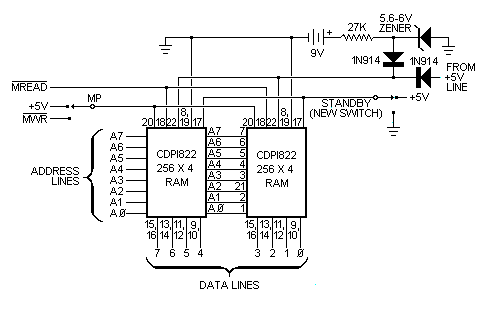
Fig. 4. Using a low-power COSMOS RAM and a 9-volt battery permits saving programs in memory.

Periodically check the battery's output; if it should fall too low, the memory system won't be able to hold data.
The last piece of hardware we will discuss here is the simple output driver shown schematically in Fig. 5. This is a conventional driver for almost anything that doesn't require more current than the transistor is capable of safely handling. The diode in the relay circuit removes the reverse transient spike that might otherwise damage the transistor. You can substitute a LED or even a load resistor for driving a power stage.
More Programming. The single-line output program shown below is a simple program that will flash the Q LED at a preset rate. It also provides a programmable square wave on the Q line.
Step   M     Bytes   Comment
  1  0000     7A     0-->Q
  2  0001  F8 10 B1  10-->R1.1
  3  0004     21     R1.1
  4  0005     91     R1.1-->D
  5  0006   3A 04    Repeat step 3 if D = 00
  6  0008   31 00    Go to step 1 if Q = 1
  7  000A     7B     1-->Q
  8  000B   30 01    Go to step 2
When you run this program, the square-wave frequently depends on the settings of the input switches. You can change frequency at any time. For higher frequencies, change B1 at M(0006) to A1 and 91 at M(0008) to 81. You can now select any of 256 different frequencies by altering the settings of the switches.
To modify the program to sweep the audio frequency range, use the following program:
Step   M     Bytes   Comment
  1  0000  F8 FF A2  FF-->R2.0
  2  0003     7A     0-->Q
  3  0004   82 A1    R2.0-->D; D-->R1.0
  4  0006   21 81    R1.1; R1.0-->D
  5  0008   3A 06    Repeat step 4 if D = 00
  6  000A   31 03    Go to step 2 if Q = 1
  7  000C  7B 22 82  1-->Q; R2.1; R2.0-->D
  8  000F   32 00    Go to step 1 if D = 00
  9  0011   30 04    Go to step 3
This program can be used in audio test applications. Note that R2 is used as a second counter that causes the square-wave frequency to change after each cycle. You can hear what this sounds like by using the circuit shown in Fig. 5.
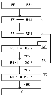
Very low frequency square waves or long-interval timing, can be programmed by cascading counters as illustrated in the following flow chart:

The Q line can then be used to activate a relay (as in Fig. 5), which can control house lights, motors, etc.
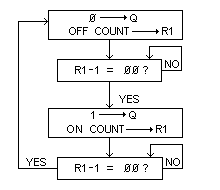
Suppose you wish to program a variable-pulse generator instead of square-wave generator. Use separate counts for the pulse off and on times as illustrated in the following flow chart:

This program will flash the Q LED and put a square wave on the Q line at a rate determined by the contents of memory M(0002) from a 10 to some other number. By referring back to the instruction Subset Table in last month's article, you should be able to interpret the above program.
Note in the program that R1 is used as a 16-bit decrementing counter (steps 3, 4, and 5). When the high- order eight bits of this counter reaches 00, the Q line goes to its opposite stage. Changing steps 2 and 4 to use the low-order byte of R1 increases the Q line's output frequency by a factor of 256.
If you use a 1-MHz crystal in the clock, the above program can generate square waves at frequencies between 0.3 and 80 Hz, depending on the byte in M(0002). By changing the B1 instruction at M(0005) to 81, square waves between 80 and 20,000 Hz can be generated. In this manner, your basic computer becomes a presettable square-wave generator.
We can rewrite the program so that the square wave's frequency becomes a function of the settings of the toggle switches as follows:
Step   M     Bytes   Comment
  1  0000  F8 FF A2  FF-->R2.0
  2  0003     E2     2-->X
  3  0004     7A     0-->Q
  4  0005   6C B1    Switch byte-->MX, D:D-->R1.1
  5  0007   21 91    R1.1; R1.1-->D
  6  0009   3A 07    Repeat step 5 if D = 00
  7  000B   31 04    Go to step 3 if Q = 1
  8  000D  7B 30 05  1-->Q; Go to step 4